Introduction
Injection molds have an indispensable industry position in the entire manufacturing industry. Many businesses usually know that a mold is needed to produce a product, but after just designing the drawings, they have no idea about the next step. In this article, we will turn your drawings into molds and learn the detailed process of turning the drawings into injection molds.

Validating the 3D Drawing
Before embarking on the intricate process of mold making, it is paramount to ensure the foundation is solid. This foundation lies within the 3D drawing, serving as the blueprint for the eventual silicone mold itself. Validating the accuracy and completeness of the 3D drawing is not merely a formality but a crucial step in guaranteeing the success of the entire manufacturing process.

Importance of Validation:
Validating the first 3D printed part drawing serves as a safeguard against potential errors and discrepancies that could compromise the integrity of the final mold. By meticulously scrutinizing every aspect of the design, manufacturers can identify and rectify any issues before they escalate into costly mistakes during the mold making process.
Key Considerations:
Dimensions: Accurate dimensions are the cornerstone of any successful mold. Discrepancies in measurements can lead to ill-fitting mold halves or misaligned features in the final cast objects. Therefore, verifying the dimensions against design specifications is paramount to ensure compatibility with the mold material intended application.
Angles:
Precision is not limited to linear measurements but extends to angles as well. Ensuring that angles are correctly represented in the 3D drawing is essential for achieving proper draft angles in the mold, facilitating easy release of the final cast objects and preventing damage to intricate details.
Intricate Details:
The devil often lies in the details, and nowhere is this more evident than in mold making. Intricate details, such as fine textures or intricate patterns, must be faithfully represented in the 3D drawing to preserve the integrity of the final cast objects. Failure to validate these details could result in loss of fidelity and diminished quality in the finished products.

In essence, validating the 3D drawing is not merely a box to be checked but a fundamental aspect of mold making that lays the groundwork for success. By paying meticulous attention to dimensions, angles, and intricate details, manufacturers can ensure that their molds are primed for precision and excellence.
Choosing the Right Software
In the realm of mold making, the choice of software can make all the difference between success and frustration. Selecting the appropriate Computer-Aided Design (CAD) software is a crucial step in the mold making process, as it lays the foundation for translating a 3D drawing into a tangible mold. Let’s delve into the considerations involved in choosing the right software and the importance of compatibility and toolpath generation for CNC machining or 3D printing.

Discussion on Selecting CAD Software:
The market offers a plethora of CAD software options, each with its own set of features and capabilities. When it comes to mold making, however, certain considerations take precedence:
Feature Set:
Opt for CAD software that offers robust tools specifically tailored for mold making. Look for features such as mold design libraries, parting line creation, and draft analysis tools to streamline the mold making process and enhance efficiency.
Compatibility:
Ensure that the chosen CAD software is compatible with the file formats commonly used in mold making, such as .STL (stereolithography) files. Compatibility with other software tools and machinery, such as CNC machines or 3D printers, is also essential for seamless integration into the manufacturing workflow.
Toolpath Generation:
CAD software should facilitate the generation of toolpaths for CNC machining or 3D printing. Toolpaths are the paths followed by cutting or additive manufacturing tools to shape the mold according to the design specifications. The ability to generate precise toolpaths is crucial for achieving accuracy and consistency in mold production.
Importance of Compatibility and Toolpath Generation:
Compatibility:
Seamless compatibility between CAD software and other components of the manufacturing process, such as CNC machines or 3D printers, ensures smooth data transfer and communication. This minimizes the risk of errors or discrepancies that could arise from incompatible file formats or software platforms.
Toolpath Generation:
The ability to generate accurate toolpaths is paramount for translating the 3D design into a physical mold. Whether using CNC machining or 3D printing, precise toolpaths ensure that the mold is fabricated with the desired level of detail and accuracy. Additionally, efficient toolpath generation minimizes production time and material waste, optimizing overall productivity.
In summary, selecting the right CAD software is a critical decision in the mold release agent and making process. By prioritizing features such as compatibility and toolpath generation, manufacturers can leverage technology to streamline their mold release workflow and achieve superior results in mold production.

Designing Mold Halves
In the intricate process of mold making, the design of mold halves plays a pivotal role in determining the success of the endeavor. Mold halves serve as the foundation supporting material upon which the final mold is built, and their design requires careful consideration of various factors to ensure optimal functionality and performance. Let’s delve into the crucial aspects of designing mold halves and explore considerations for parting lines, draft angles, and venting to facilitate casting material flow.
Exploring Crucial Aspects:
Parting Lines:
Parting lines delineate the boundary between the two halves of the mold and determine how the mold will be separated for casting. It is imperative to carefully plan the location of parting lines to ensure that they align with the contours of the object being molded and minimize the need for excessive finishing work on the final cast.
Draft Angles:
Draft angles are critical for facilitating the release of the final cast object from the mold without damage. By incorporating draft angles into the design of mold halves, manufacturers can ensure smooth ejection of the cast object and prevent the formation of undercuts that could impede demolding.
Venting:
Venting is essential for facilitating the flow of casting material throughout the mold cavity and ensuring that air bubbles are expelled during the casting process. Proper venting helps prevent defects such as voids or trapped air pockets in the final cast and contributes to the overall quality and integrity of the molded object.
Considerations for Facilitating Material Flow:
Parting Lines:
Strategically placing parting lines along areas of minimal detail or aesthetic importance can streamline the mold making process and reduce the complexity of mold design. Additionally, incorporating features such as tapered surfaces or fillets along parting lines can facilitate smooth demolding and minimize the risk of damage to the final cast.
Draft Angles:
When designing mold halves, it is essential to incorporate sufficient draft angles to ensure easy release of the cast object from the casting molds. The ideal draft angle will vary depending on factors such as the type of cast material amount of casting material, surface finish requirements, and the intricacy of the design. Careful consideration of these factors is crucial for achieving optimal demolding performance and minimizing the risk of defects in the final cast.
Venting:
Effective venting is essential for ensuring uniform material flow throughout the mold cavity and preventing the formation of defects such as air bubbles or voids in the final cast. When designing mold halves, it is important to incorporate venting channels or vents at strategic locations to facilitate the escape of trapped air during the casting process. Proper venting not only enhances casting quality but also contributes to the longevity and performance of the casting mold.
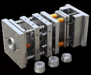
After everything is processed according to the drawings, the components will be assembled. After assembly, there will be a flying mold process to check whether the mold closing is good. If it is not in place, repairs will be required. Until the assembly is OK, the injection molding machine will be tested. Generally, the mold will be tested three times T1, T2, and T3. If there is no problem, it can basically be mass-produced. If there are any unqualified parts in each mold test, it will be reviewed and modified before the next mold test is carried out.
After the injection molded parts of the test mold pass the QC inspection, the mold is qualified and can be produced.
In conclusion, designing metal casting mold halves requires careful consideration of factors such as parting lines, draft angles, and venting to ensure optimal functionality and performance. By paying attention to these crucial aspects, manufacturers can create investment casting molds that facilitate smooth material flow, minimize defects, and produce high-quality cast objects with precision and consistency.

Conclusion
In this comprehensive guide, we have traversed the intricate landscape of mold making, from the initial validation of 3D drawings to the generation of toolpaths and simulation of the manufacturing process. Throughout this journey, several key points have emerged, underscoring the importance of meticulous planning, precise execution, and a deep understanding of mold making techniques.
In closing, mold making is both an art and a science, requiring a blend of technical expertise and creative ingenuity. With the right tools, knowledge, and mindset, you can unlock the potential of mold making and bring your designs to life with precision and excellence. Happy molding!


