Classification of flow pattern
(1) Snake flow pattern: When the melt enters the mold cavity from the gate, it produces a jet effect and behaves like a snake on the surface of the product, so it is called a snake flow pattern.
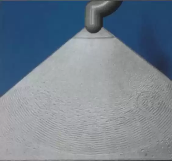
(2) Wave pattern: the melt flow in the mold cavity is not smooth, sometimes fast and sometimes slow, which is like a wave on the surface of the product, so it is called a wandering pattern.
(3) Radiation pattern: generally only appears in the vicinity of the gate, the melt into the mold cavity to produce jets, manifested in the product surface for the radiation, so-called radiation pattern.
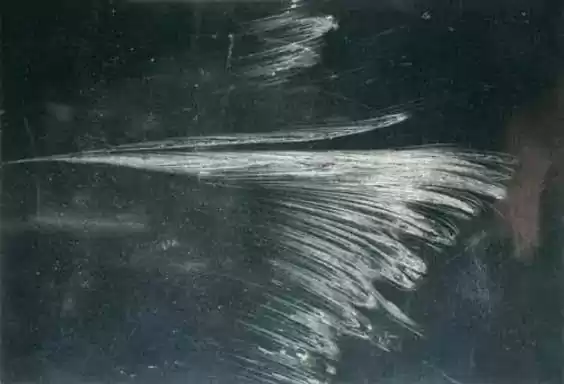
(4) Fluorescent pattern: the shear stress generated by the flow of melt makes the surface of the product produce a luster very similar to the body of a firefly, so it is called the fluorescent pattern.
Solution for the flow pattern
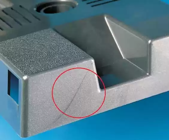
1)Snake flow pattern
When the gate depth is much smaller than the cavity entrance depth, and the mold filling rate is high, the melt flow becomes unstable jet flow, and the jet in front of it has solidified and the flowing melt behind it fills the cavity, then a serpentine flow pattern appears on the surface of the product.

Solution measures:
1. Change the process conditions: The method of lowering the injection rate will gradually eliminate the jet effect and make the melt flow in an extended way, and the extended flow will make the product have better surface quality.
2. Change the mold gate size: When the depth of the gate is slightly smaller than the depth of the mold cavity, the exit expansion of the jet makes the melt behind and the front edge of the jet not far from the outflow fuse, so that the jet effect is not obvious.
When the gate depth is equal to or close to the cavity depth, the mold filling rate is low and the extended flow is formed.
3. Change the mold gate angle: Make the angle between the mold gate and mold moving mold 4o~5o so that when the melt flows out from the gate, it will be stopped by the mold cavity wall first, which can prevent the appearance of a snake flow pattern.
4. Change the position of the mold gate: Set the mold gate at the closest position to the injection mold cavity wall (perpendicular to the direction of the gate), so that when the melt flows out from the gate, it will be stopped by the mold cavity wall first, which can also prevent the jet from appearing and become an extended flow, thus avoiding the appearance of snake flow pattern.
2)Wavy pattern
During the melt filling process, the new melt flow is continuously pressed out from the inner layer, pushing the front wave stagnant flow to move, while the front wave edge is constantly stretched, and the melt pressure rises later due to the flow resistance and flattens the wave pattern just formed in front, resulting in the accumulation of stagnant flow and the formation of the wave pattern on the surface of the product.
Especially in the case of a fast injection rate, small injection pressure, or unreasonable mold structure, the melt flow stops when it enters and the PP crystallization is fast and slow, which is more likely to cause inconsistent crystallization on the surface of the product and form wavy lines on the surface of the product.
Solution measures:
1. Change the process conditions. Adopt high pressure and low-speed injection, which can keep the stability of melt flow of molten mass and thus prevent the appearance of wavy lines.
2. Increase the mold temperature. As the mold temperature increases, the melt flowability increases. For crystalline polymers, a higher temperature is beneficial to the uniformity of crystallization, thus reducing the appearance of wavy lines.
3. Change the mold cavity structure. The structure of the injection mold can also cause the appearance of wavy patterns on the surface of the product.
For example, if the angles of the mold core are more prominent, the melt flow resistance is higher, which will cause melt flow instability, thus forming a wave pattern.
Therefore, changing the corners of the mold core to make a buffer transition and keep the melt flow stable can prevent the appearance of wavy lines.
4. Change the thickness of the product. Uneven thickness of the product will make the melt flow resistance sometimes large and sometimes small, resulting in unstable melt flow, so try to design the thickness of the product as uniform thickness, which can also prevent the appearance of wavy lines
3)Radiation pattern
When the injection rate is too large and the melt is ejected, the melt has elasticity, so when the melt flows quickly from the barrel to the cavity through the injection mold gate, the elasticity of the melt recovers too quickly, causing the melt to rupture and produce radiation patterns.
Solution measures:
Change the process conditions. Adopt high pressure and low-speed injection to increase the flow time of the elastic melt in the same flow length and increase the degree of elastic failure, to reduce the appearance of the radiation pattern.
Change the mold gate shape. Enlarging the gate or changing the gate to a fan shape can make the elasticity of the melt recover slightly before it enters the mold cavity to avoid melt rupture.
Lengthen the length of the main sprue of the mold. It can also avoid melt breakage by making its elasticity fail before the melt enters the mold cavity.
Replacement of equipment to extend nozzle. Lengthen the flow path of the melt before proceeding to the mold cavity, so that the elastic failure of the melt is increased, which can also avoid the radiation pattern due to melt rupture.
4)Fluorine pattern
When the melt flows in the injection mold cavity, one end of the molecular chain close to the solidification layer is fixed to the solidification layer, while the other end is stretched by the neighboring molecular chain in the flow direction.
As the melt near the cavity wall has the highest resistance to flow and the lowest flow rate, and the center of the cavity has the lowest resistance to flow and the highest flow rate, a velocity gradient is formed in the flow direction. The surface of the product will show glow lines.

Solution measures:
1. Change the process conditions: With the increase of the injection rate, the cooling time of the melt in the same length of the flow branch is reduced, and the solidification of the melt per unit volume becomes slower so that the internal stress of the product is weakened and the appearance of fluorescent lines on the surface of the product is reduced.
2. Increase the mold temperature: Higher mold temperature can make the macromolecule relaxation accelerate, and molecular orientation and internal stress are reduced, thus reducing the appearance of fluorescent lines on the surface of the product.
3. Change the cavity structure and increase the thickness of the product: The thickness of the product is larger, the melt cooling slower, the stress relaxation time is relatively long, and the orientation stress will be reduced, thus reducing the fluorescent pattern.
4. Heat treatment (oven baking or hot water cooking): Heat treatment intensifies macromolecular movement and shortens relaxation time, which strengthens the unorientation effect and thus reduces fluorescence lines.