The shape, number, size, and position of gates in a mold can have a great impact on the quality of plastic parts. Therefore, the selection of a gate is one of the key points of plastic mold design.
The main roles of the gate are
- After the cavity is filled, the melt will first condense at the gate to prevent it from backflowing.
- It is easy to remove the tail material of the gate.
- For multi-cavity molds, it is used to control the position of the fusion mark.
The type of gate is generally divided into two types: non-restrictive gates and restrictive gates.
Restrictive gates are divided into 3 series, such as side gates, point gates, and disc ring gates.
1. Non-restrictive gate. The non-restrictive gate is also called a straight gate (as shown in Figure 1).

Its characteristic is that the plastic melt flows directly into the cavity, the pressure loss is small, the feeding speed is fast and the injection molding is easy, it is suitable for all kinds of plastics.
It has the advantages of good pressure transfer, strong pressure retention and shrinkage, simple and compact mold structure, and convenient manufacturing.
However, it is difficult to remove the gate, and the gate marks are obvious; the heat concentration near the gate is slow to condense and easy to produce large internal stress, and also easy to produce shrinkage pits or surface indentation. It is suitable for large plastic parts, thick-walled plastic parts, etc.
2. Restricted gate. The cavity and the manifold are connected by a channel with a short distance and a small cross-section.
The main types of restrictive gates are
1. Point gate:
The pointed gate is a circular gate with a very small cross-section.
The characteristics of a pointed gate are:
a. Small restriction of gate position.
b. Small residual marks after gate removal, which do not affect the appearance of the molded part.
c. The gate can be automatically pulled off when the mold is opened, which is conducive to automatic operation.
d. Small stress caused by the sprue attachment filler.
The disadvantages are large pressure loss, the mold must adopt a three-plate mold structure, complicated mold structure, and sequential injection mold splitting mechanism, also can be applied to a two-plate mold structure without runners.

2. Latent gate:
Latent gate evolved from the point gate, the manifold is opened on the parting surface, and the gate is submerged under the parting surface and enters the cavity in the oblique direction.
In addition to the characteristics of the point gate, the feed gate is usually hidden on the inner surface or side of the injection molded parts, so it does not affect the appearance of the molded part, and the molded part and the runner are set to push out the mechanism separately.

3. Side gates: Side gates, also called edge gates, are generally opened on the parting surface and feed from the outside of the cavity (molded part).
The side gate is a typical rectangular cross-section gate, which can easily adjust the shear rate and gate closing time during mold filling, therefore it is also called a standard gate.
The characteristics of the side gate are
Simple gate cross-sectional shape, easy processing, and precise machining of the gate dimensions; flexible selection of the gate position to improve the filling condition; correction without having to remove the mold from the injection molding machine. Easy to remove the gate and small traces.
Side gates are especially suitable for two-platen multi-cavity molds. However, it is easy to form defects such as fusion marks, lock holes, and depressions and has high injection pressure loss and poor exhaust for shell-shaped parts.

4. Overlapping gate, also called a lap gate, is the same as a side gate, but the gate is not on the side of the cavity but one side of the cavity.
It is a typical impact gate that effectively prevents the injection flow of the plastic melt. If the molding conditions are not proper, surface pits can be created at the gate. Removing the gate is difficult and leaves a visible gate mark on the surface of the injection molded parts.

5. Fan gate is a variation of the side gate, which is used to mold large-width plate parts. The gate is gradually widened in the direction of feeding and the thickness is gradually reduced to the thinnest.
The plastic melt is evenly distributed in the width direction, which can reduce the internal stress and warpage of the molded part; the cavity has good exhaust volume to avoid surrounding air. However, it is difficult to remove the gate and the trace is obvious.
6. Flat slit gate, also known as a sheet gate, is a variation of a side gate and is often used for molding large flat parts. The distribution runner of the gate is parallel to the side of the cavity, called a parallel runner, and its length can be greater than or equal to the width of the molded part.
The plastic melt is evenly distributed in the parallel flow channel and then flows parallel to the cavity at a low linear velocity, which results in low internal stress and reduces warpage deformation due to orientation and good cavity venting. However, the workload of gate removal is large and the traces are obvious.
7. Disc gates are used for cylindrical plastic parts with a large bore, or plastic parts with a large square bore. The gate is on the entire perimeter of the bore.
The molten plastic melt enters the cavity from the perimeter of the bore at approximately the same speed, so that the part does not produce fusion marks, the core is evenly stressed, and the air is removed in sequence. For our products, disc gates are rarely used.


8. The circular gate is set on the outer side concentric with the cylinder cavity, i.e. The plastic injection molding gate is set around the cavity, so it can be called the outer circular gate, and its gate position corresponds to the inner disc gate.
It is suitable for thin-walled long tube line plastic parts. Since the melt enters the mold cavity evenly around the core, the mold is filled evenly, the exhaust effect is good, and there are no fusion marks on the part.
However, it is difficult to remove the gate, and leaves obvious gate marks on the outside of the part. Circular gates are mostly used in small, multi-cavity molds.
9. Spoke and claw gates are similar to disc gates in scope and are also suitable for parts with the rectangular bore, but the entire perimeter feed is changed to several small arcs or straight lines.
Therefore, it can be regarded as an inner gate. This gate is easy to remove, the flow channel is less condensed, and the upper part of the core is positioned to increase the stability of the core, but the fusion marks on the part affect the strength and appearance quality of the part.
The claw gate is a variation of the spoke gate, which opens a runner in the conical section of the core. It is mainly used for long tube-shaped plastic parts with small bores or plastic parts with high coaxiality requirements.
The location and number of multiple gates often determine the appearance quality and performance of the product, so when choosing the location and number of gate types.
The following points should be followed
1.The gate should be located in a position that can make all corners of the cavity filled at the same time;
2.The plastic injected into the cavity should maintain a uniform and stable flow rate in all stages of the injection process.
3.The gate should be set in the thick part of the product wall thickness, so that the melt from the thick section into the thin section, facilitates the replenishment, to ensure the complete filling of the mold.
4.The location of the gate should be chosen so that the plastic filling process is the shortest to reduce the pressure loss.
5.The location of the gate should be chosen in the part of the cavity conducive to the exclusion of gas.
6.The gate should not make the melt directly into the cavity, otherwise, it will produce swirling flow, leaving traces of spin on the plastic parts, especially since the narrow gate is more likely to have this defect.
7.Consider the possible melt marks, bubbles, depressions, deficiency, insufficient injection, and spraying material.
8.The location of the gate should be chosen in the part where the fusion pattern can be avoided on the surface of the product. When it is impossible to avoid the fusion pattern, the location of the gate should be chosen considering the suitability of the part where the fusion pattern is generated.
9.The location of the gate should be chosen to prevent the production of the fusion line on the surface of the plastic, especially in the case of circular or cylindrical plastic parts, the cold material well should be added at the melt pouring of the face of the gate.
10.The setting of the gate should avoid the phenomenon of melt fracture.
11.When the projection area of the product is large, avoid opening the gate on one side to prevent the uneven force of the injection molding process.
12.The gate should be set in the part that does not affect the appearance of the product
13.Do not set the gate in the part of the product which is subject to bending load or impact load, generally, the strength near the gate is the worst.
14.The location of the gate of the injection mold with a long and thin core should be far away from the molding core so that the molding core will not be deformed by the flow of material;
15.Large or flat plastic parts forming, to prevent warping, deformation, and lack of material can be used compound gate.
16.The operation of the sprue should be as easy as possible, preferably with the automatic operation;
It is the common type of gate in production. In production, according to the product structure, product appearance requirements, and different needs of automation, the following types of gates are used.
Straight gate
In our common plastic crates, due to their large structure size, there is no special requirement for an appearance gate, so they all adopt straight gates with simple structure and easy processing, but it is difficult to remove the material handle. As shown in Figure 12.

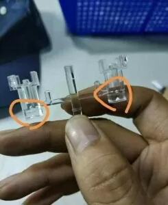
Side gate
For some transparent parts, the side gate is used because the front and back sides are not allowed to have a gate position (as shown in Fig. 13), but it cannot meet the automatic production and needs to trim the material handle manually.
Latent gate
The latent gate is the most used gate type in our injection mold. Most of our functional parts switch fixed frames, etc. use the latent gate type with the gate on the outside, while most of the product shells use the submerged gate type with the gate on the inside.
This type of gate can automatically drop the material to meet the automation requirements and leave no gate marks on the product surface.

The commonly used gates are the above, but there are some special types of gates applied depending on the product requirements.
Generally speaking, when determining the type of gates, we should take into account the requirements of all aspects, and we can use one kind of gates or a combination of different gates in a set of injection molds, with the ultimate goal of producing qualified products.